Pixel Shading
What is a shader? I'll give Ben Cloward's definition:
"Code that controls the color of each pixel on the screen."
Doesn't get simpler than that. Ben Cloward's YouTube is a great resource and, in addition to the video I just linked, I recommend this introductory lesson on what shaders are actually doing:
One of the key points covered in these videos is that, in the past, shaders included both surface properties (like color or roughness) and lighting properties (like shadows or reflections), but in modern rendering pipelines, shaders generally just supply the surface properties, and the engine simulates the light.
In addition, for beginners, here are three videos from the Bad Decisions Studio about Materials in Unreal Engine:
- Tutorial Part 6: Intro to Materials & Textures
- Tutorial Part 7: Materials & Textures Basics
- Tutorial Part 8: Materials & Textures Advanced
What is the difference between a Material and a shader? Materials are Unreal Engine's implementation of surface shaders. This page in the documentation gives an overview. Notice that they capitalize the word Material, the same way they capitalize Nanite or Lumen. The "Material" system is what lets you create, edit, and apply shaders to objects.
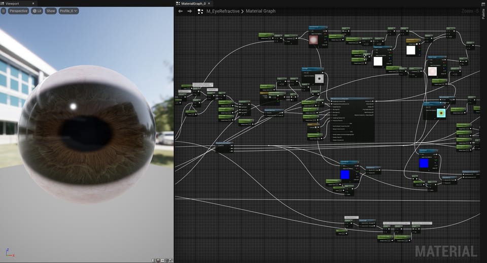
Shaders define many surface properties, like base color (aka albedo, or diffuse), roughness, metallic, normals, etc. This can be done entirely with code, but most shaders designed to replicate real-world surfaces will also sample texture maps. In the Basics of PBR video I linked above, at around 23:40, there is a simple demonstration of texture maps being applied to a shader.
The bare-bones setup Ben Cloward uses in this example, connecting Texture Sample nodes directly to the root shader node, is often all that is required to make a good-looking Material. More sophisticated Materials, like Quixel Megascans, include many parameters to tweak the shader's appearance, but most of the impact comes from the high quality texture maps. Any Megascans surface Material comes as a Material Instance, and they all reference the same Master Material. The only difference between the Instances is which textures are slotted in.
MetaHumans also use complex skin shaders, but simply editing the textures found in the body and face Material Instances can drastically alter their appearance.
For a more in-depth look at texture maps, here is Ben again:
How does a 2D texture get mapped onto a 3D object? Texture coordinates, often called UVs, are the link between 3D geometry and the textures that enhance their surfaces. When I started out, this was one of the topics I had the most trouble understanding. So, I am going to spend some time explaining it... maybe for my own sake.
Texture coordinates are a pair of coordinates on a flat plane, like the X and Y coordinates you remember from algebra class. The only reason they are referred to as U and V is so they aren't confused with the X and Y already being used to describe 3D space. X, Y, and Z define a vertex's position in 3D space, while U and V define the vertex's position in a separate 2D space.
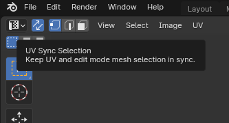
A simple way to visualize this is to open a new Blender project with the "default cube" in the scene and open the UV Editing workspace. After enabling UV Sync Selection, any vertex selected in either the 3D Viewport or the UV Editor will be highlighted in both windows.
UV coordinates range between 0 and 1. In the UV Editing workspace, open the sidebar and click the Image tab to see the "UV Vertex" values, displayed here as X and Y:
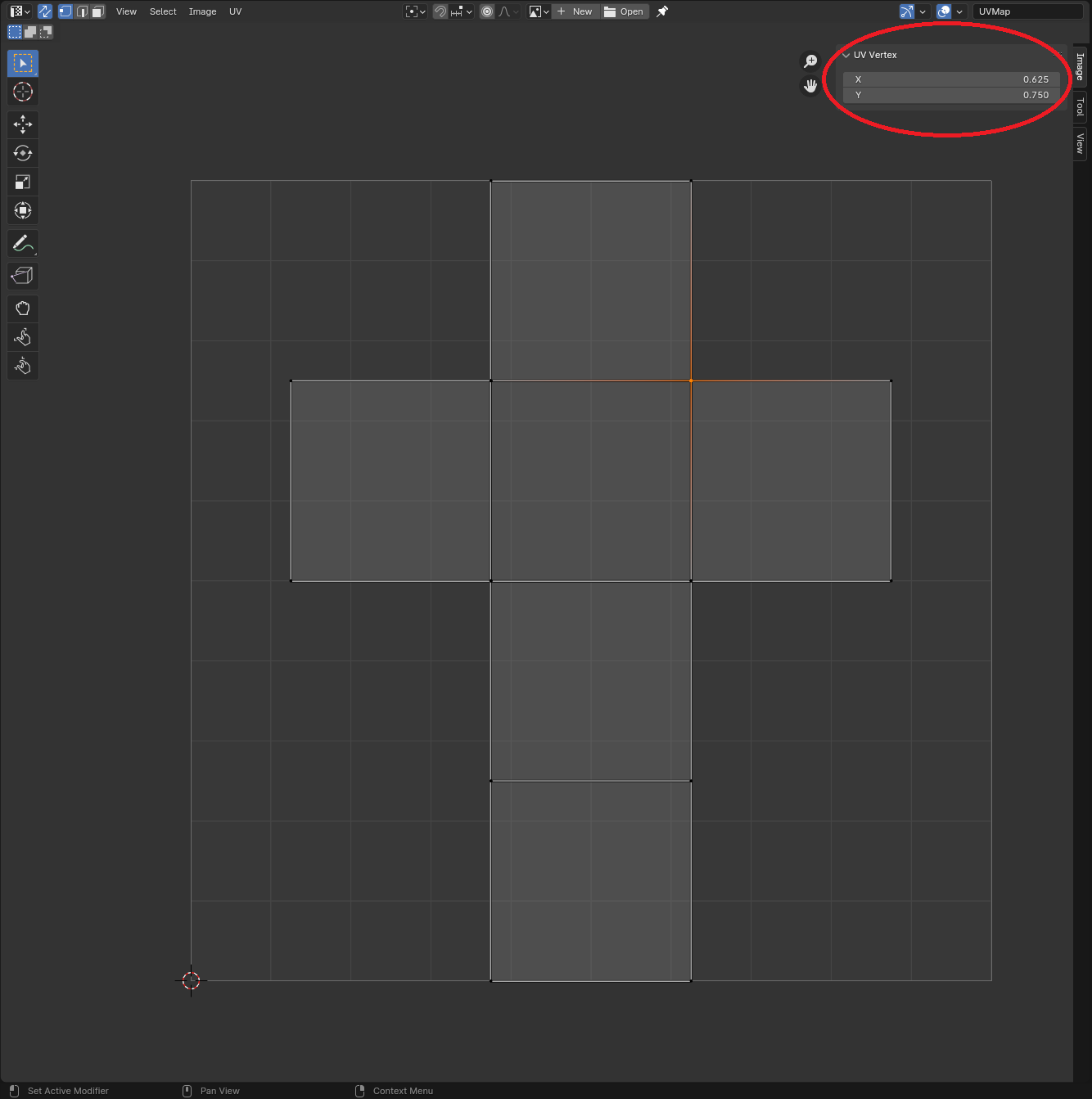
In this grid, the bottom left corner is 0,0 and the top right corner is 1,1. The selected vertex's UV coordinates are 0.625, 0.750. UVs are normalized between 0 and 1 because a shader might sample texture maps of varying pixel resolutions. This way, whether the texture sampled is 4K or 1K, the vertex's UV coordinate can be assigned a pixel.
The simple formula is:
Texture Width * U, Texture Height * V
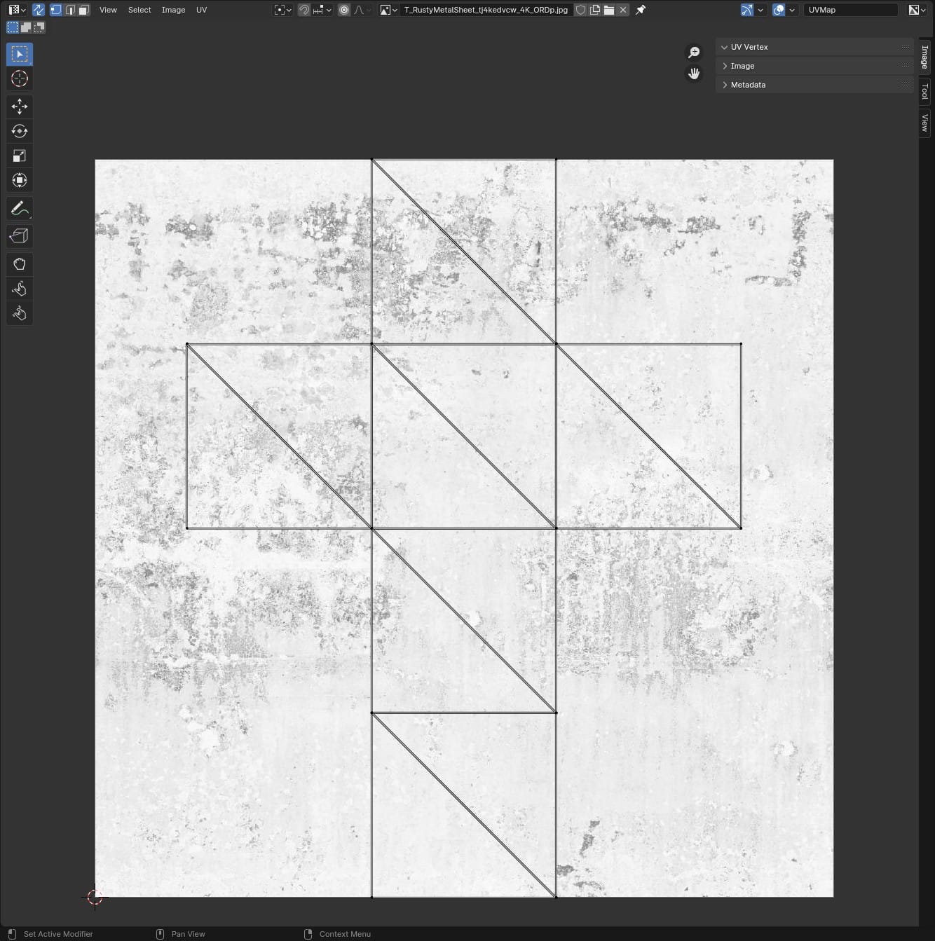
In this cube example, I'll add a 4K texture file to the UV Editor. (Images placed in a UV Editor serve as a visual reference only. They have nothing to do with what textures are actually applied to the object's surface.)
Again in the sidebar, click the View tab and check "Pixel Coordinates," then return to the Image tab. The UV Vertex values will now read in pixels, in this case: 2560, 3072.
The 4K texture resolution is 4096 x 4096, so these pixel coordinates make sense.
(4096 * 0.625), (4096 * 0.750) = 2560, 3072
If I replace the texture with a 1K version, the cube's position in the UV space is unchanged, but the pixel coordinates now read 640, 768.
(1024 * 0.625), (1024 * 0.750) = 640, 768
Ok, so we see how a vertex's UV coordinates translate into a pixel on a texture map, but what about all the pixels between the vertices? At render time, the engine interpolates between the vertices. In the above screenshots, Blender is displaying the cube mesh in quads, but render engines work in triangles, so from the perspective of the renderer, the cube looks more like this...
...and the interpolation happens within those triangles.
Here are two more videos (by guess who) that elaborate on texture coordinates and the graphics pipeline (which includes the vertex-to-pixel interpolation I mentioned above).
- Texture Coordinates - Shader Graph Basics - Episode 8
- The Graphics Pipeline - Shader Graph Basics - Episode 2
For simple shapes like the cube, 3D applications will automatically create a UV map for them, which is why I could open a fresh Blender project and immediately view the cube's faces laid out in the UV Editor. More complex shapes will need to be "unwrapped" and often require manual positioning in UV space.
Unwrapping a mesh can be tedious, but is fairly intuitive. Here is a guide.
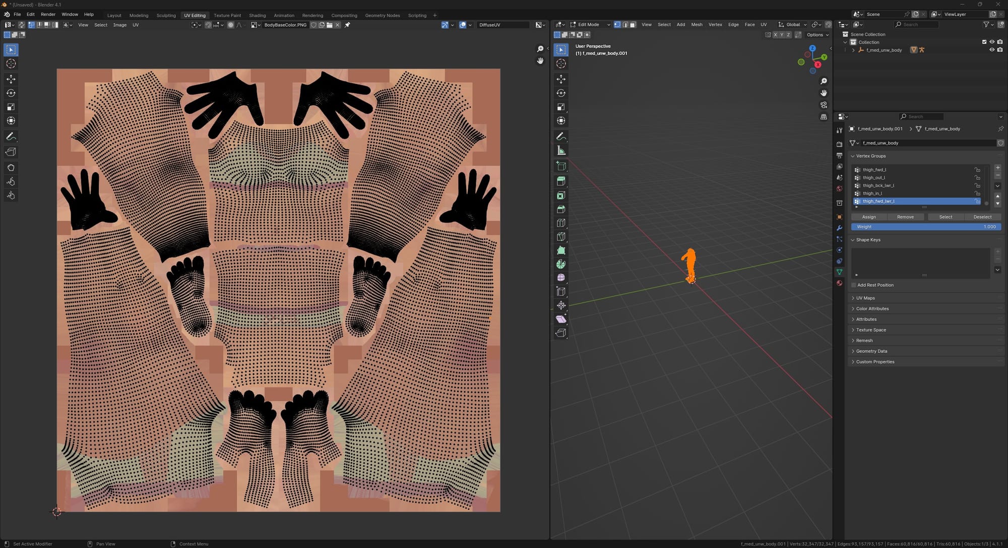
Also, texture coordinates are included in formats like FBX. Here is the MetaHuman body mesh, exported from Unreal Engine and imported into Blender and viewed in the UV Editor, with the body texture map behind it.
As for this movie project, I don't expect I will be building many shaders from scratch. Megascans are good to go. When I use photogrammetry, the textures that come with the 3D mesh can be plugged directly into the Material root node. Same goes for textures I find on the internet. But, it would be nice to build some functionality around the texture samples, so that I can tweak their appearance in the Material editor.
ali.3d has a video where he builds one of these "master materials" with various parameters to modify the sampled textures.
This is a good way to go. In my case, I just repurpose the Megascans main surface material, M_MS_Srf.
Note: the following applies to Megascans downloaded from the new Fab marketplace. Older Megascans, downloaded from Quixel Bridge, have a different node graph. But, this method can be applied to either.
The M_MS_Srf Material is set up to take four texture maps:
- Albedo
- ORM (Occlusion, Roughness, Metallic)
- Normal
- Displacement
In Megascans surface materials, the displacement/height map is not functional by default, so I ignore it here.
Albedo and Normal are straightforward to swap out, since the Material is already set up to sample one texture map per node.
ORM is tricky. It has three black/white texture maps packed into a single three-channel RGB texture image. The photogrammetry apps I've tried don't provide packed textures like this. Websites like ambientCG don't either. They provide one map per texture file.
I decided the most versatile setup would be to duplicate the M_MS_Srf and, in a custom version, split the ORM texture sample into three nodes:
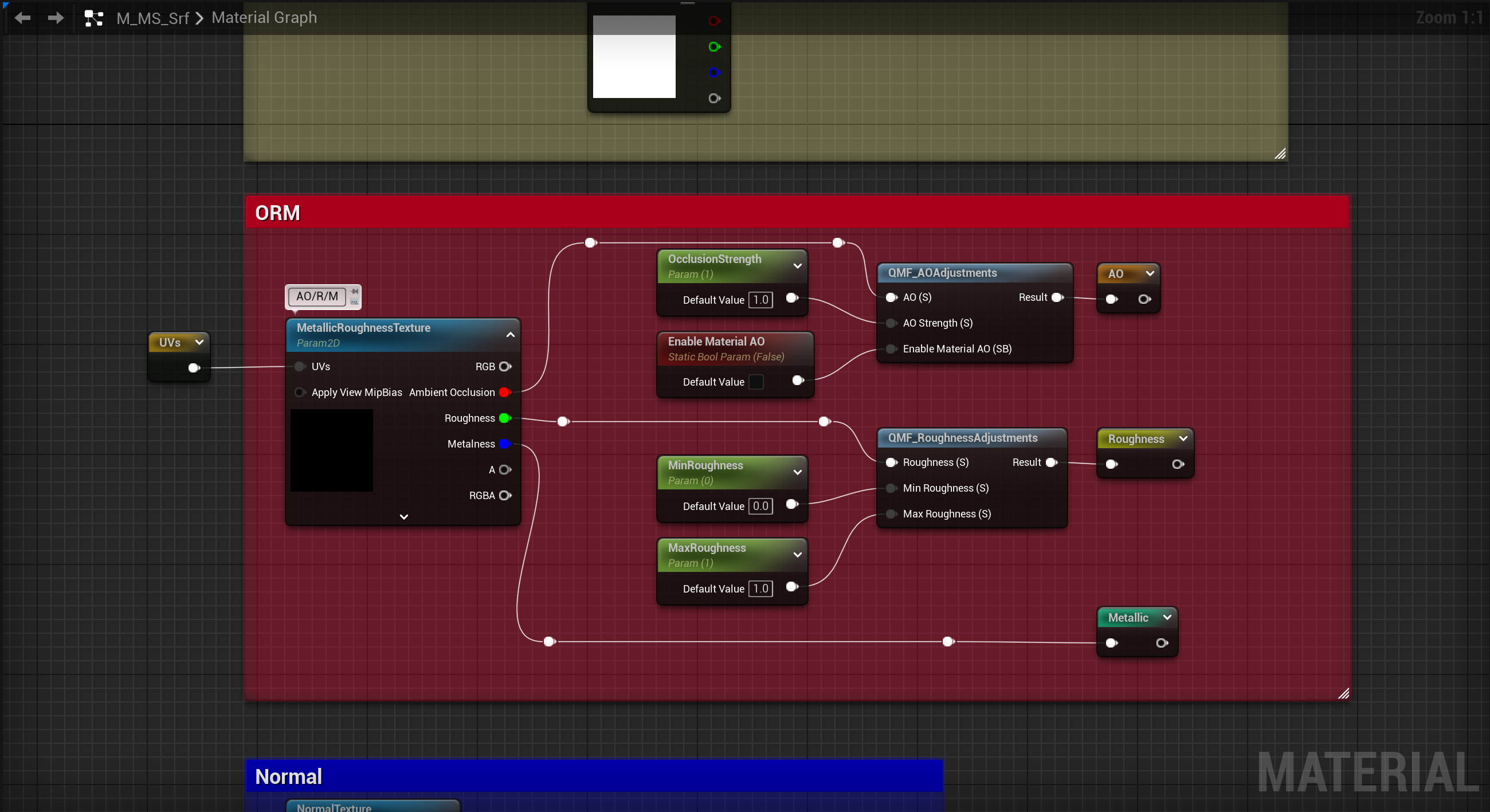
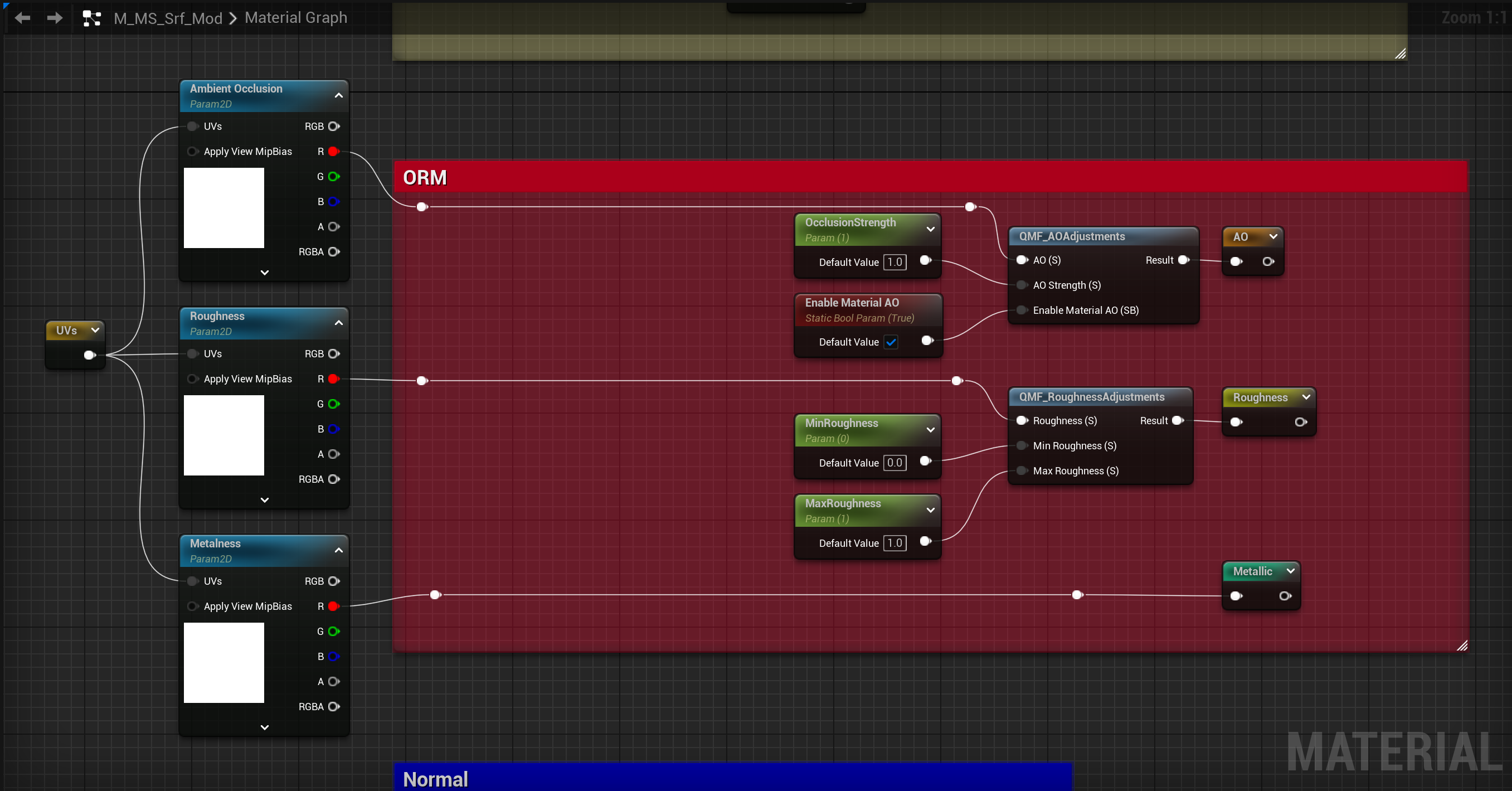
Left: Original, Right: Modified
Instances created from this modified Material have three texture slots in the ORM section of the parameters, ready for the AO, roughness, and metallic maps to be slotted in.