Sculpting with Nodes
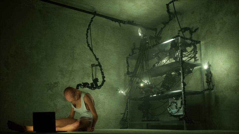
This movie is about two people who connect their minds, first experiencing each other's senses, and finally merging into one consciousness. I want to put the audience inside that experience. For example, what would it be like to see through two pairs of eyes on opposite sides of a room? Or opposite sides of the planet? How would a single mind merge those images? How could I show that on screen? In this story, the technical details of how to wire two brains together are less important.
But, the device they plug their brains into is a crucial part of the film's aesthetic, even if its inner workings go unexplained. I imagined a tiny apartment and a cramped workroom with a bulky computer rack that the characters cobbled together themselves. Since my original plan was to actually shoot this movie in my apartment, it needed to be something that I could build from cheap (junk) computer parts. Before I pivoted to making the movie in Unreal Engine, I had pieced together a good portion of this... thing:
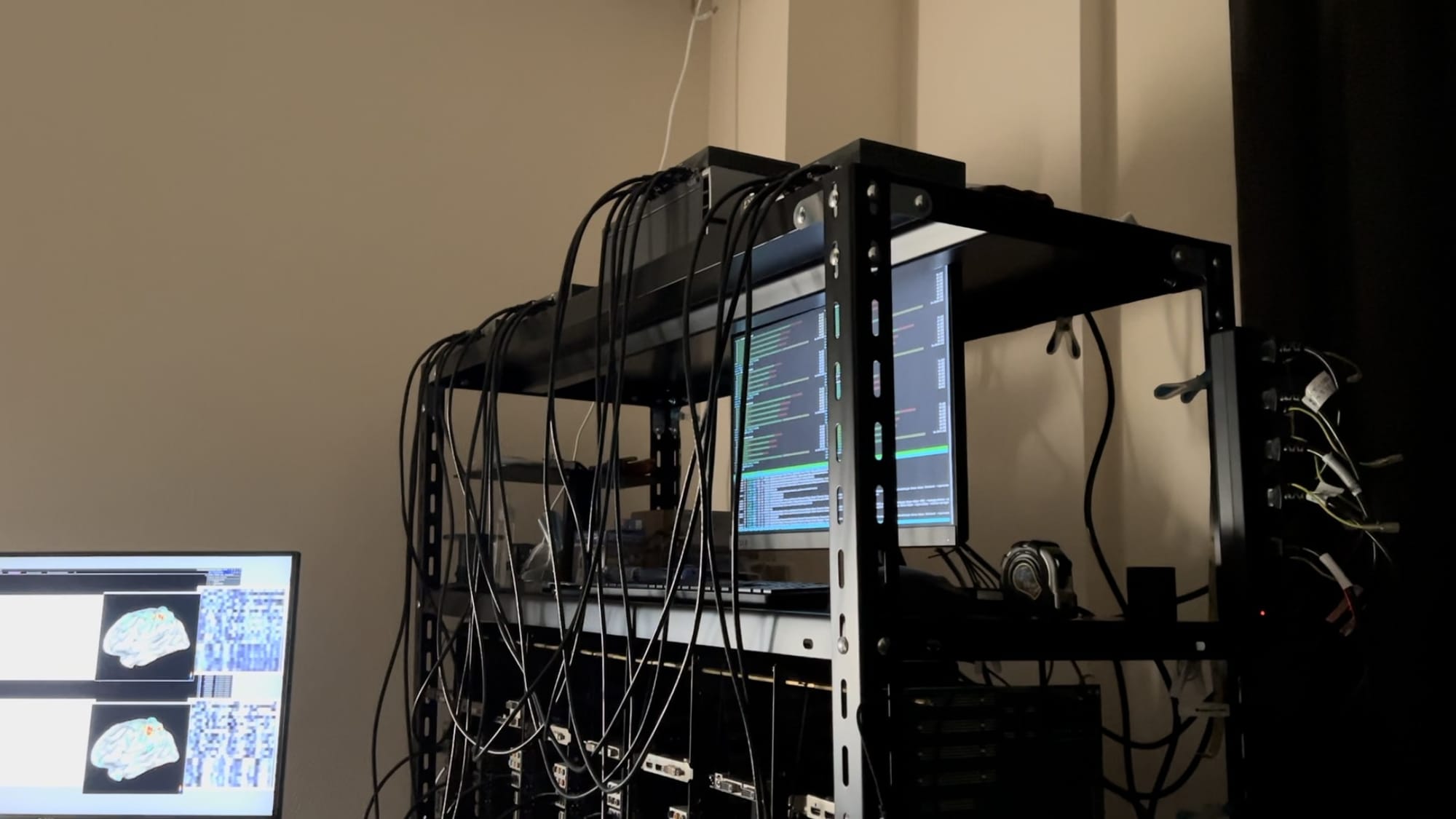
The basic structure was rows of motherboards, held together with brass spacers, all connected through a stack of network switches and Ethernet cables. This is essentially what I recreated in 3D for a brief "alpha test" video.
Around the time I was building the prop cluster computer in my living room, I read the NY Times article about using Midjourney to create fake stills from Alejandro Jodorowsky's unfinished Dune adaptation. I decided to prompt Midjourney with a description of my movie and see what came out. Here are some of the better ones:

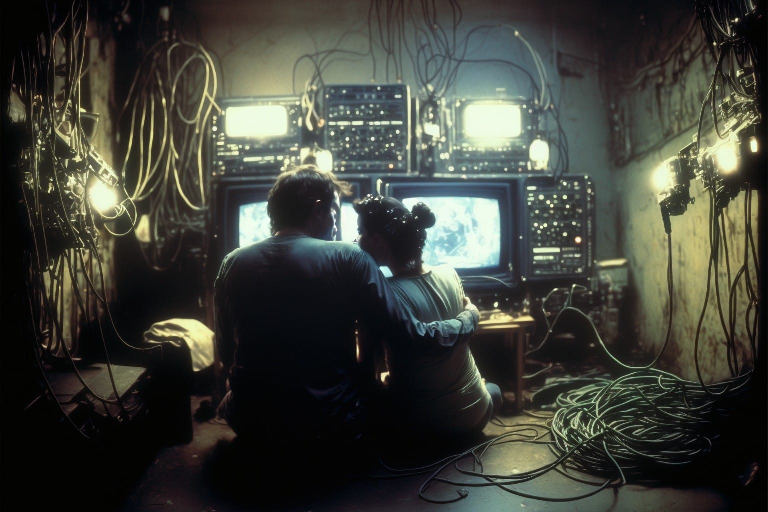
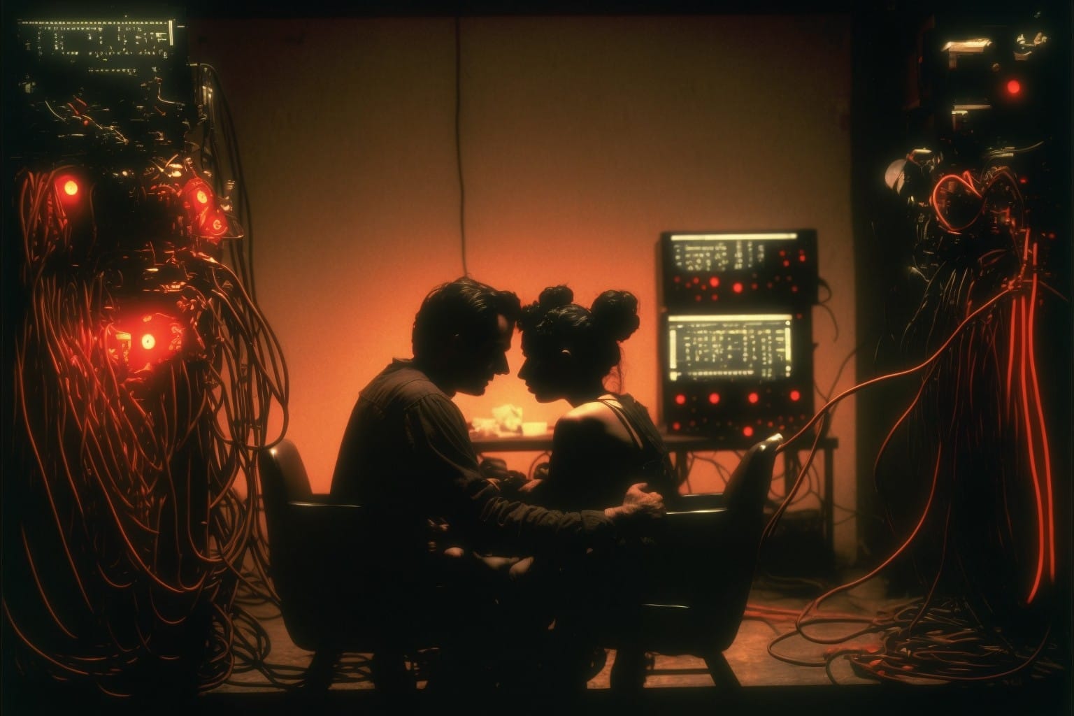

This is an early version of Midjourney and there is a fair amount of AI-jank in the images, but I like how it went wild with the nonsensical computer hardware and cables that seem to spawn and spread like vines throughout the scene. I thought it would be fun to put something this bizarre in the movie. If I never explain how the machine works or how it was built, why not make it look weird and inexplicable? Unfortunately, building something like this in the physical world was beyond me, so I carried on with my simple design.
Months later, after switching to Unreal Engine, I reconsidered the possibility of adding this dose of surrealism to the movie. My gut told me that UE's procedural generation tools could create something like the tangled monster imagined by Midjourney. Rather than designing every detail myself, building a PCG (Procedural Content Generation) rule set and letting the engine generate something spontaneous would better capture the spirit of this metallic organism.
Study Time
Before I could even think about the cluster computer, I had to get a grasp on the basics of procedural generation in Unreal Engine. These resources were helpful for me...
This is a simple, beginner-friendly tutorial by David Edwards, posted on the Epic Games community forum:
Adrien Logut, a programmer working at Epic Games, also has a tutorial on the community forum. This starts with the basics, but also goes into more complicated subjects:
Chris Murphy did a talk at Unreal Fest Prague 2024 that covers basic as well as more advanced PCG techniques:
He also wrote an article that gives a high-level view of what is possible with PCG in Unreal Engine and some of its key functionalities:
Learning Time
Working through those guides gave me a decent foundation, but when I opened my first blank PCG Graph, I realized I still had no idea how to make this thing.
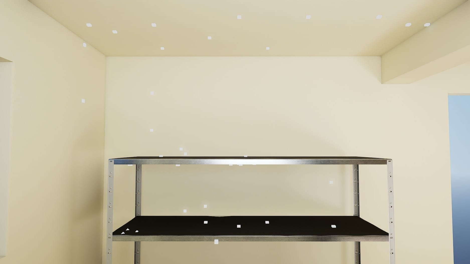
I had a PCG Volume covering an empty room with a metal rack in one corner:
My vision was that some kind of growth, resembling tentacles or vines or a slime mold, would cover the steel shelves and the floor/walls/ceiling around them. These strands would be comprised of tiny bits of hardware, like from a PCB put through a wood chipper, and at random points along the strands, bigger hardware chunks would "sprout" out into larger structures. Then, at random points between the tendrils and larger structures, rubber cables would spawn.
Originally, my philosophy was to art-direct as little as possible. I would make only the core mesh components (the computer hardware chunks, big and small), and let procedural generation do the rest.
My strategy was to get a large sample of points covering the rack and the walls around it, give the PCG Graph rules to create random pairs of those points, then spawn a spline between each of those pairs. From those splines, the graph would sample additional, densely packed points and spawn the small computer-chunk meshes from those. These would be the tendrils. Then, it was just a matter of picking random points along those tendrils to spawn the larger structures.
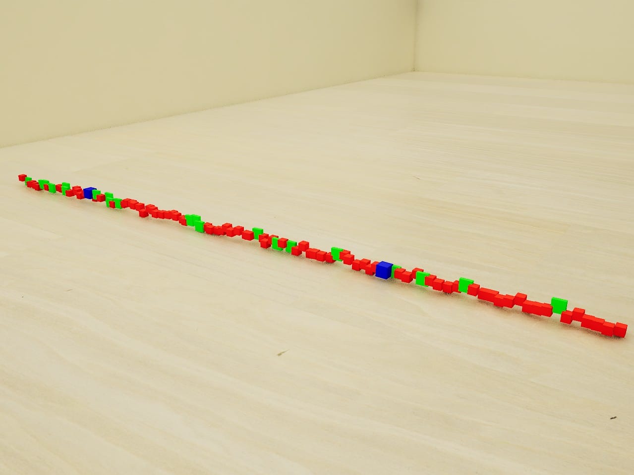
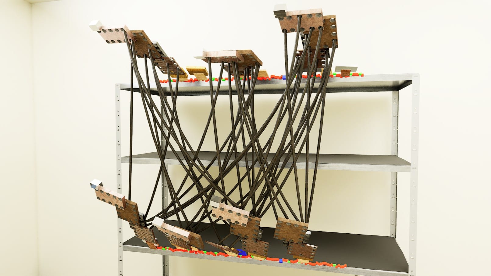
I experimented with the PCG Graph before I made the component meshes, so the first iterations used placeholder meshes. The placeholders were just cubes of roughly the size I expected the actual mesh to be, each with a distinct color, so that I could easily see how the meshes were distributed.
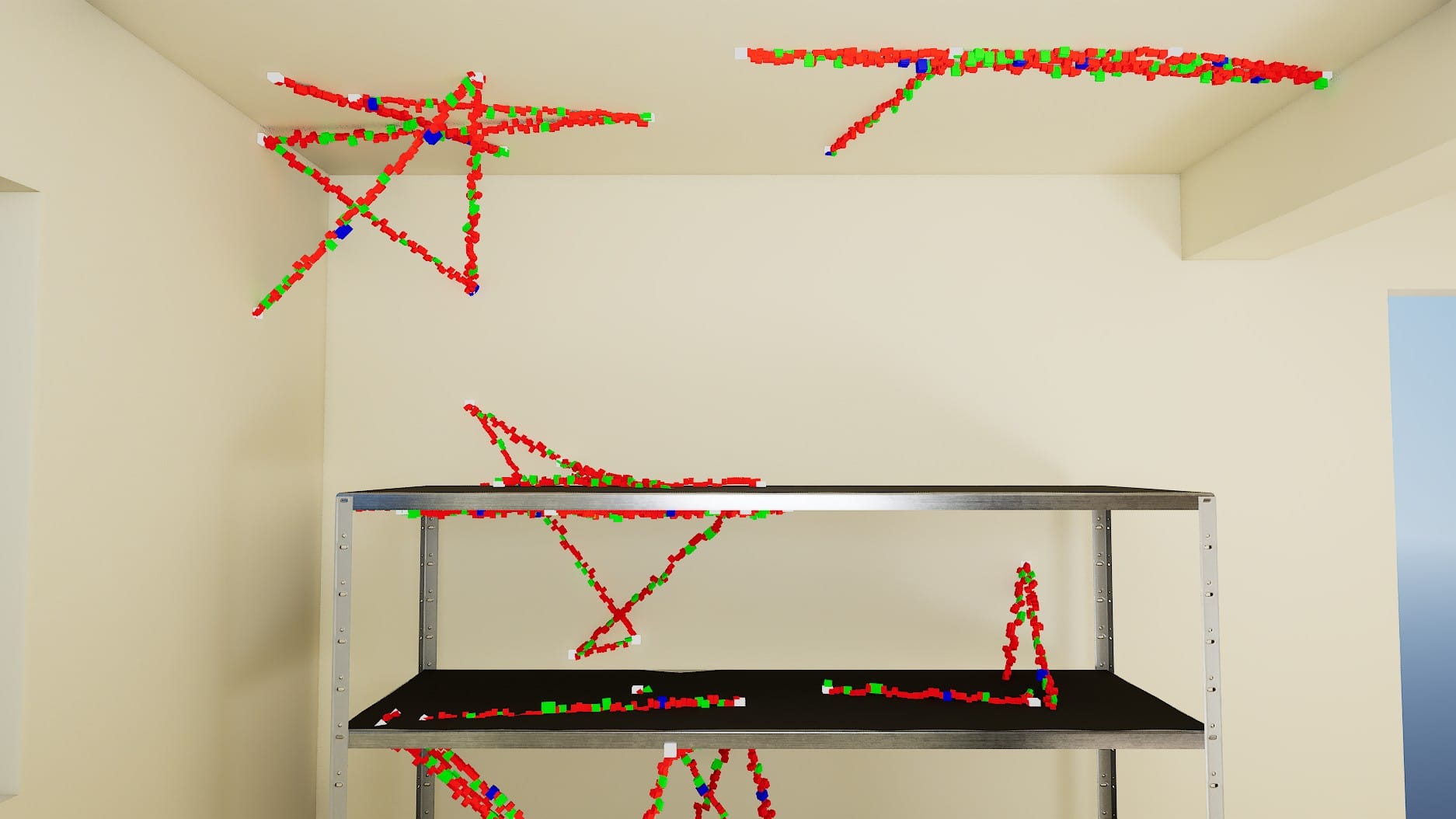
Points generated by ray casting. Then, the splines generated between those points, with meshes spawned along the splines.
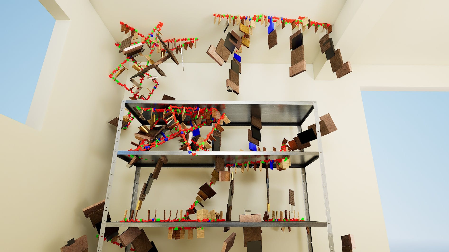
I won't cover the details of how I tried to implement this, because it was a dead end. Maybe I will try again in the future, but for the first version of the cluster computer, I abandoned this method.
One reason was that, while I managed to sample points across the shelves and walls and spawn splines between them, I wasn't happy with the formations. Another problem was that the larger mesh stacks often overlapped with the rack, the walls, and of course the other spawned meshes. I added rules that pruned a fair amount of overlapping meshes, but that doubled the complexity of the PCG Graph, and still didn't catch 100% of the offenders.
It is (probably) possible to solve these problems, but as a beginner, I couldn't find the solution this time. So, I simplified my strategy. I would draw the splines on the rack and the walls myself, and feed those splines to the PCG Graph. If I was careful with the placement, overlapping meshes wouldn't be an issue.
Like with my previous blog posts, I decided against giving a full, step-by-step explanation of my PCG Graph. I imagine most people will not be interested in copying my weird cluster computer idea, so many of my specific choices won't apply to other projects. Also, many of my choices are probably inefficient and/or flat out wrong from a best-practices standpoint. For example, parts of my PCG Graph probably could have been redone in a Subgraph, but I barely touched Subgraphs this time around.
So, while I won't cover every detail, I will cover the main problems I needed to solve and give a summary of how I solved them, along with links to more detailed resources.
Tendril Splines
The first tutorial I mentioned above includes a video that explains how to make a basic spline Blueprint and draw a multi-point spline.
With my splines drawn, I used these nodes to sample them:
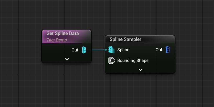
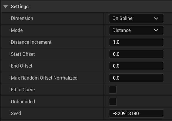
Because my splines were different lengths, and I needed them to be populated with the same density of points regardless of their length, I sampled by Distance rather than Subdivision or Number of Samples:
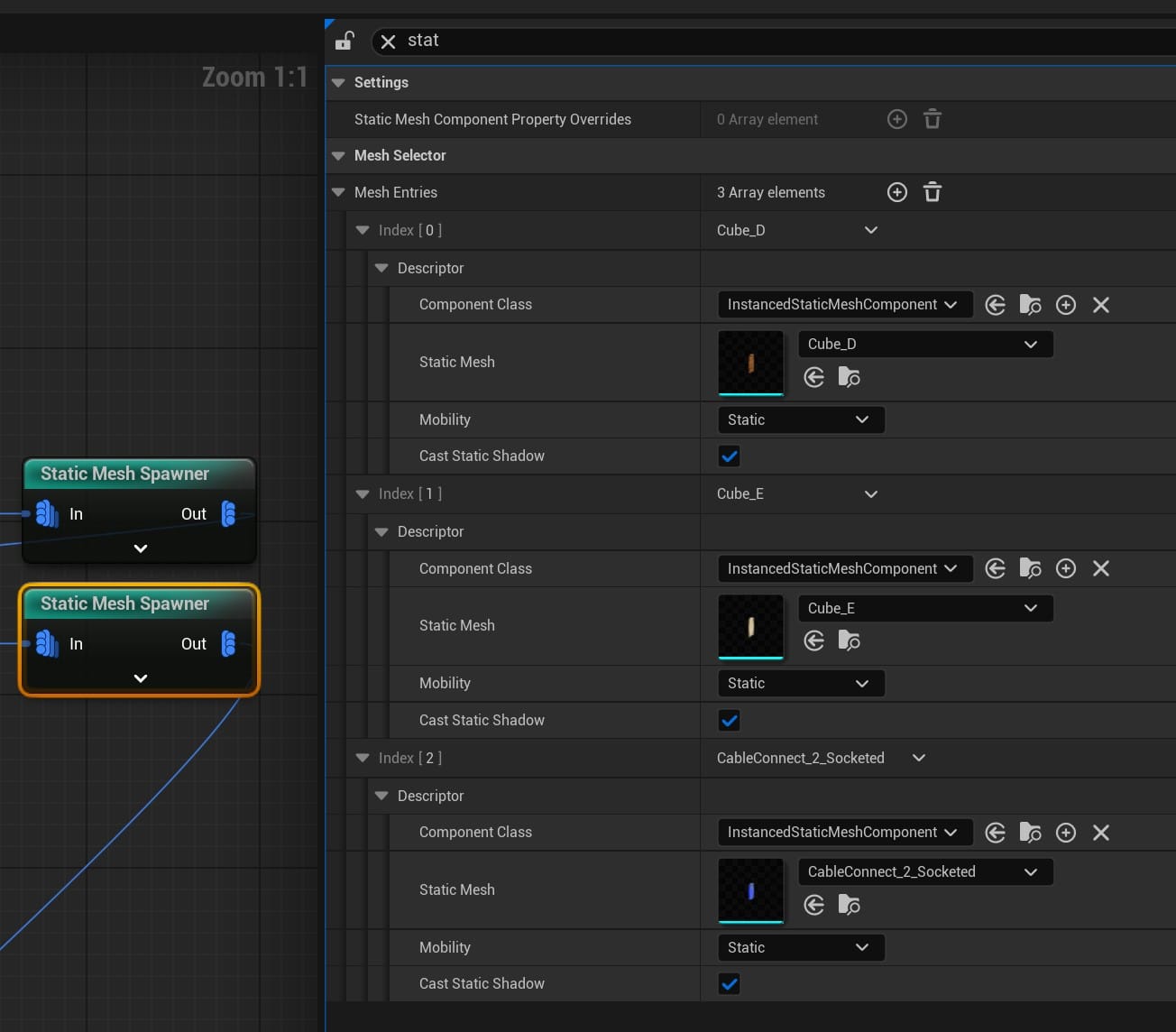
These are the nodes I used for spawning meshes from the points:
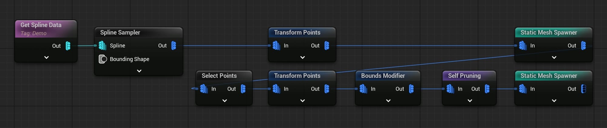
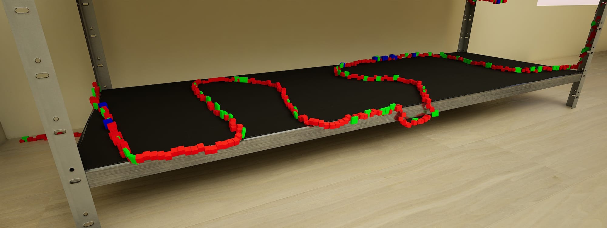
For the first group of meshes (in this case, my red, green, and blue placeholder cubes) I was okay with them overlapping, so I went straight from a Transform Points node (to give a little variety to their position and rotation) into the Static Mesh Spawner.
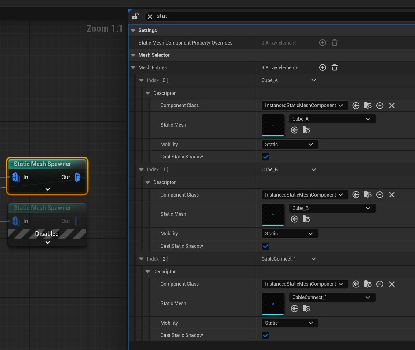
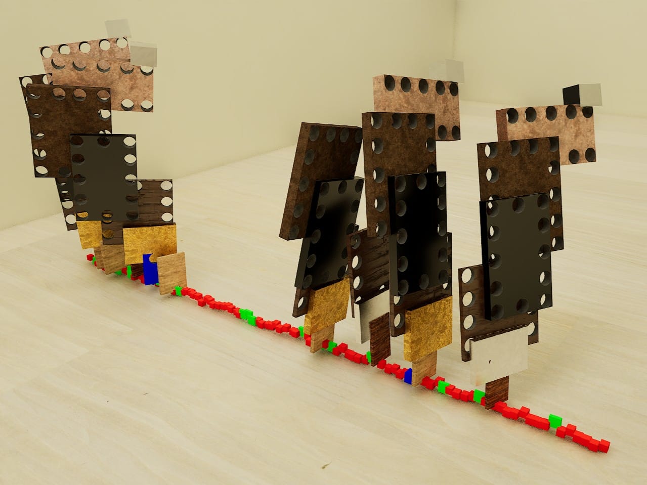
The three meshes created by the first Static Mesh Spawner, populated in a ratio set by their "Weight" value.
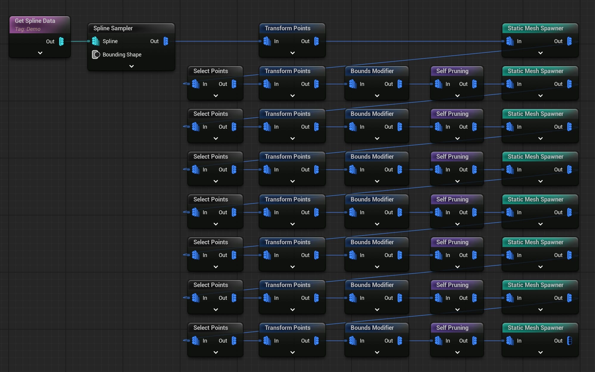
For the next layer of meshes, I used Select Points to choose a small ratio of the previous points, Transform Points again to add some position variance, then Bounds Modifier with Self Pruning to cull overlapping meshes.

From here, I could repeat the same row of nodes to add a new set of meshes to the "stacks" growing out of the tendrils.
Cable Sockets
I wanted cables to spawn between scattered points on the tendrils and stacked meshes. To create those points, I added sockets to all the meshes and used the Mesh Sockets to Points node. This method is covered in this Unreal Fest 2023 talk by Daryl Obert:
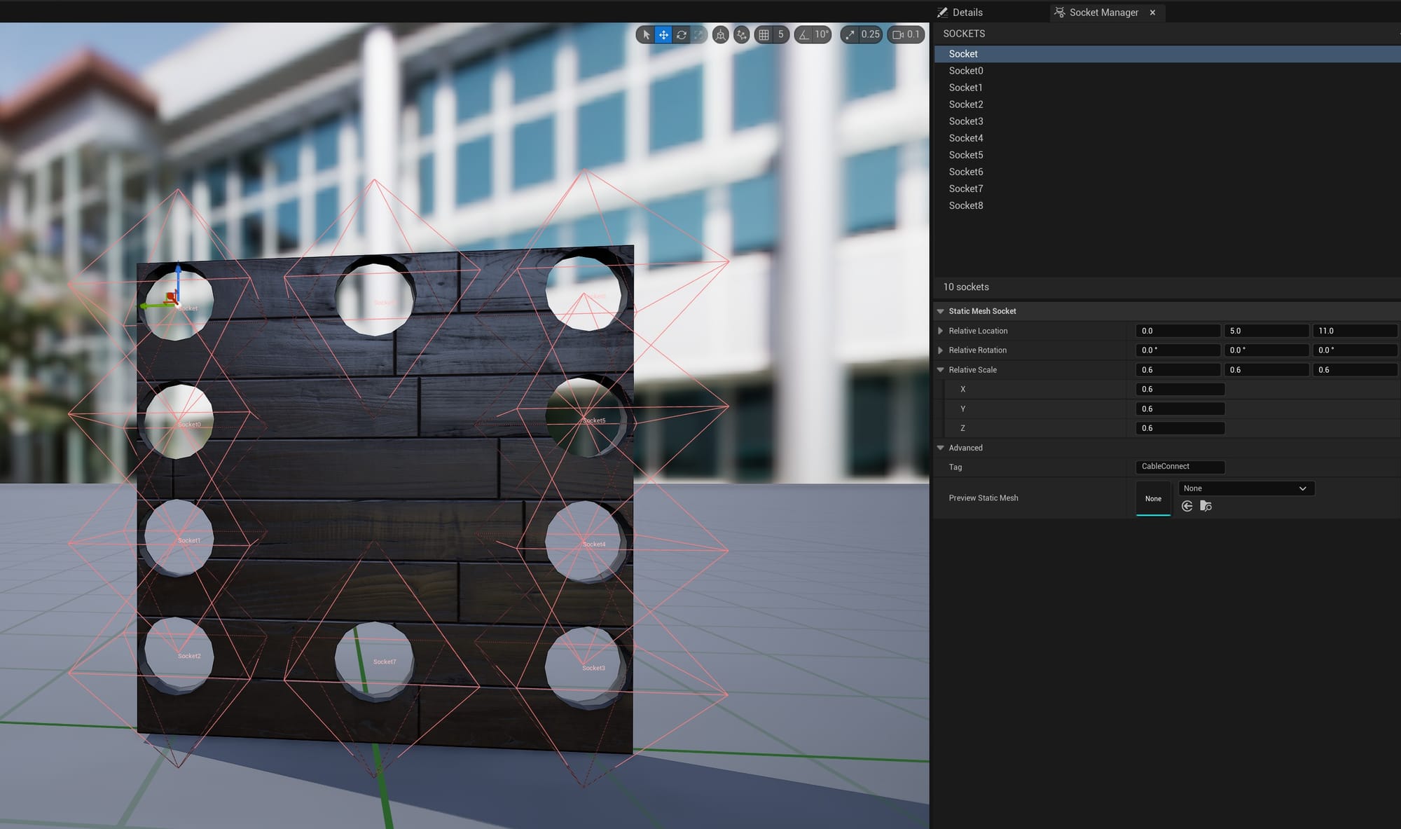
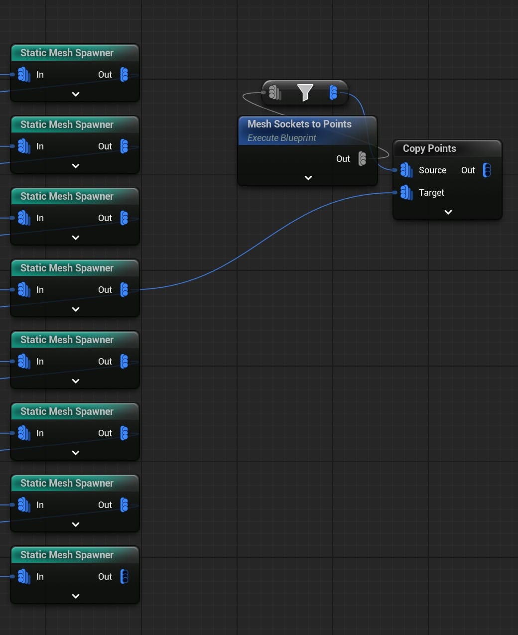
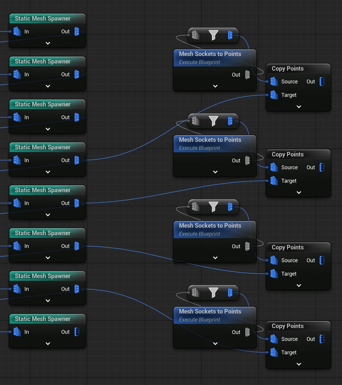
The Copy Points node is necessary because when the Mesh Sockets to Points node samples a mesh's sockets, it spawns the points at the world origin. In the screenshot above, I added sockets to a mesh called Cube_H. If I sample the sockets on Cube_H and plug the Static Mesh Spawner node for Cube_H into Target on Copy Points, the socket-points will appear in the correct position on every instance of Cube_H spawned by the PCG Graph.
For every mesh I want to add socket-points to, I will need to connect this node pair.
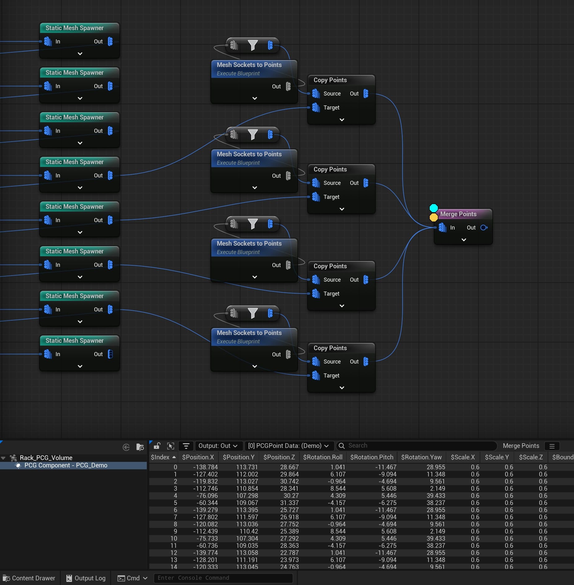
And, because I want all the socket-points to be in one pool so cables can potentially spawn between any of them, I use a Merge Points node.
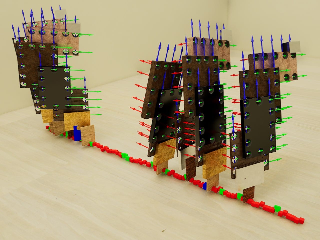
At this point I'll mention the two most useful hotkeys for PCG: 'D' to Debug and 'A' to Inspect. Any beginner tutorial will mention them, including the tutorials I linked above, and for good reason. Selecting a node and pressing 'A' will open a table of all the points generated and/or modified by that node. Pressing 'D' will spawn a small mesh at all the points' locations in the level, to make them easy to find. Also, double-clicking a point in the Inspect list will move the editor viewport to focus on that point's location.
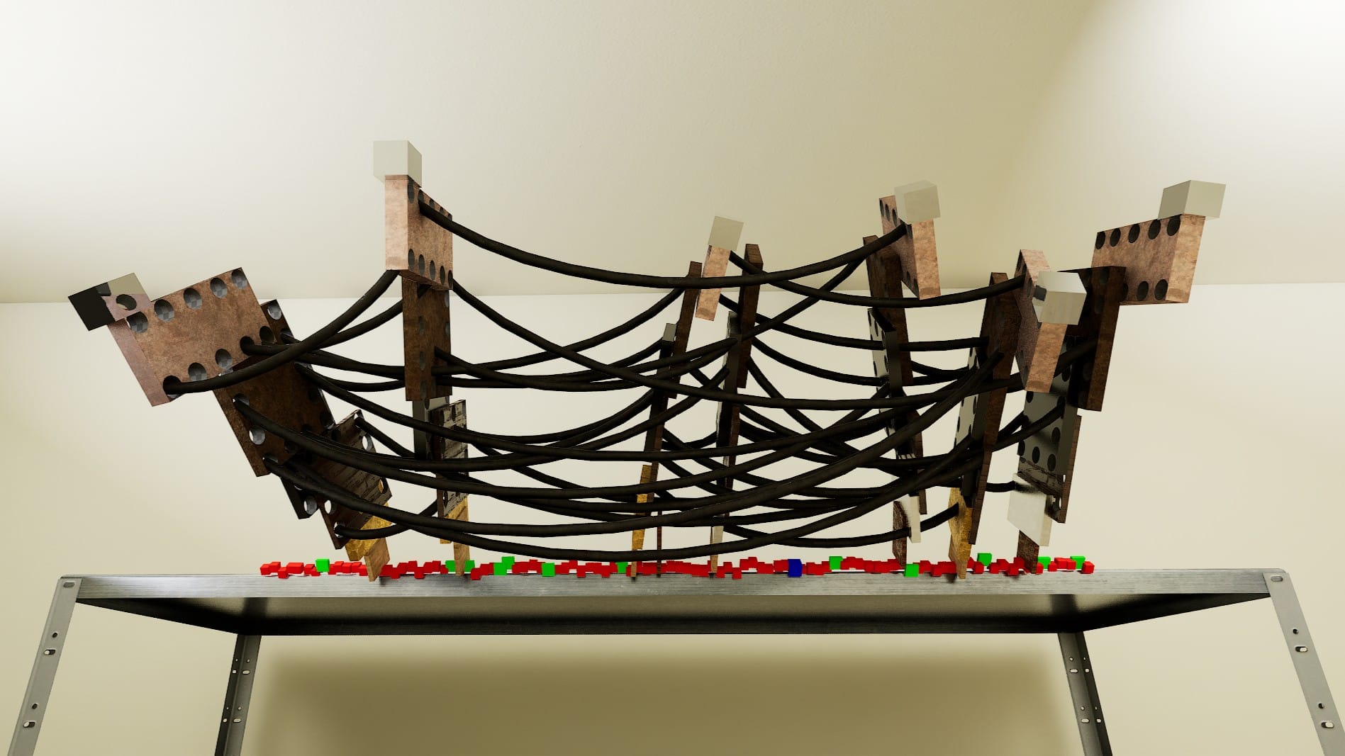
For example, the left screenshot below shows the table of all the socket-points gathered by the Merge Points node, and the right screenshot shows their locations on the actual meshes. By default, 'D' will generate a small gray cube at the points' locations, but this debug object can be changed to any mesh. In this case, I am using the PCG_AxisTripod because it sticks out more.
Cable Splines Between the Cable Sockets
I had my pool of points and I wanted some cables between them. Those cables would be generated along, once again, a lot of splines. A spline needs a minimum of two points. How would I divide this long list of points into pairs? I was stumped. But, after digging through the Unreal Source Discord, I found the obvious solution: divide by two!
Technically, divide their Index values by two.
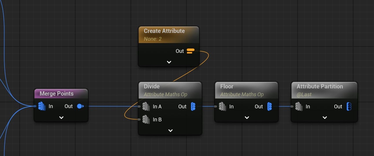
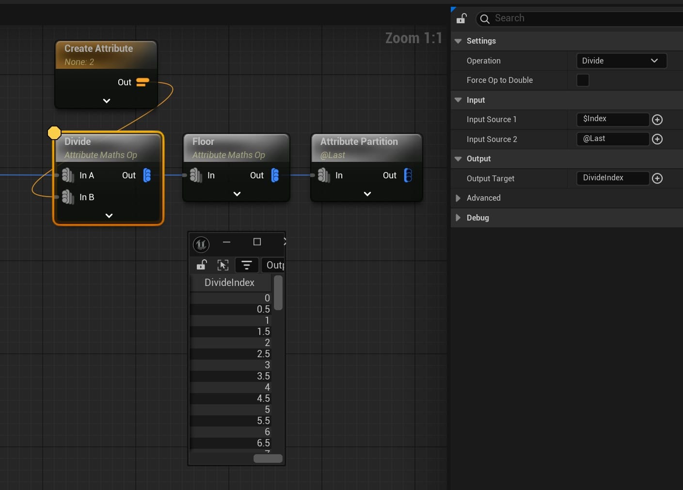
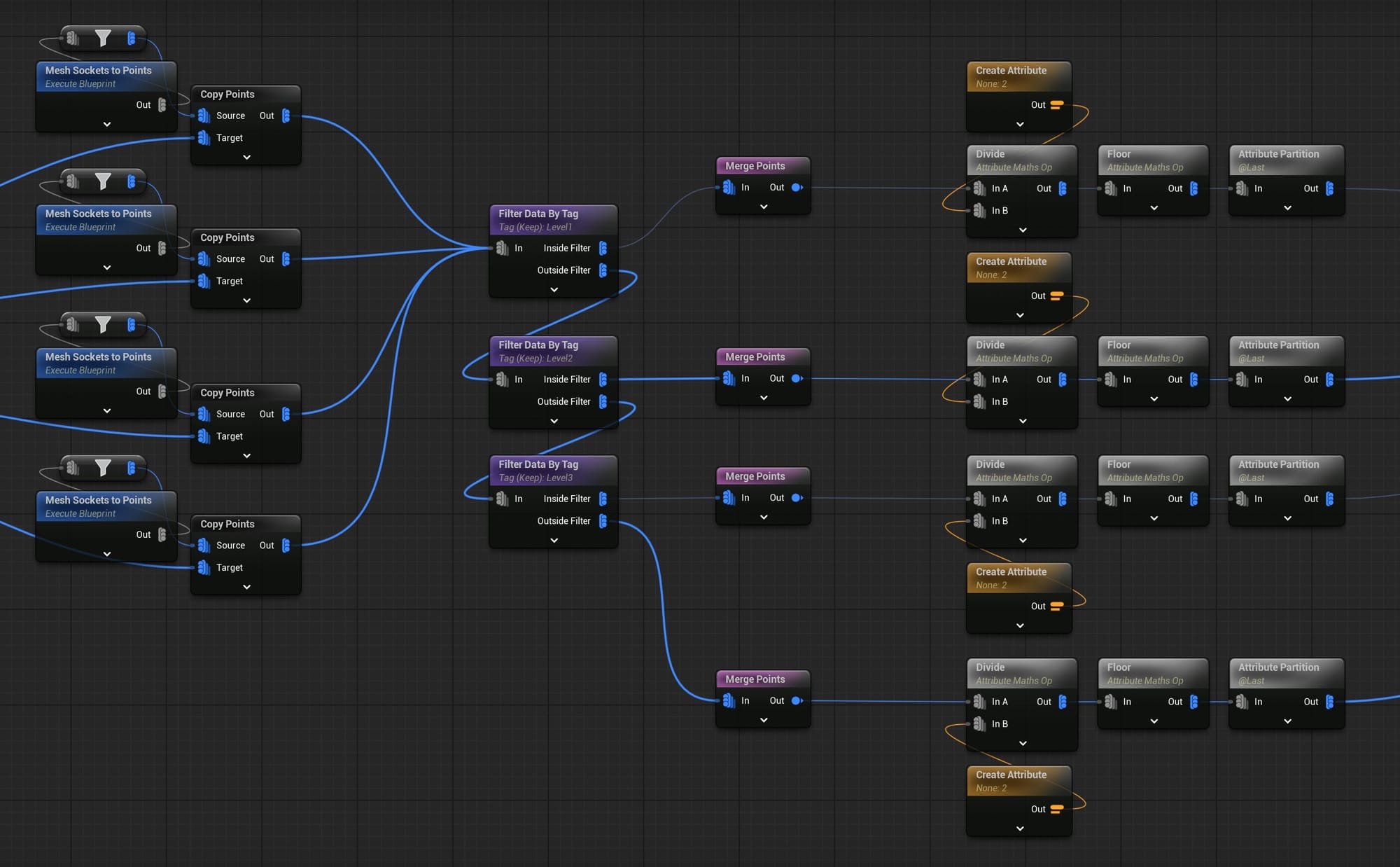
This set of nodes does the following:
- Divide the Index value by 2 and put the result in a new attribute called DivideIndex.
- Do a Floor operation on all the DivideIndex values.
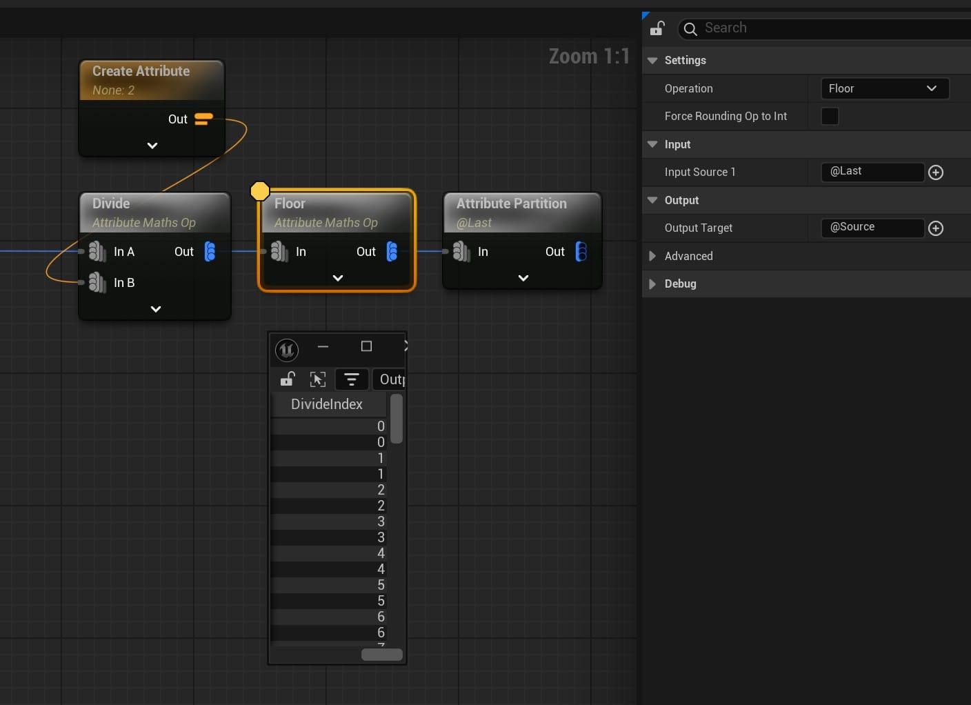
- Partition the points using the floored DivideIndex attribute.
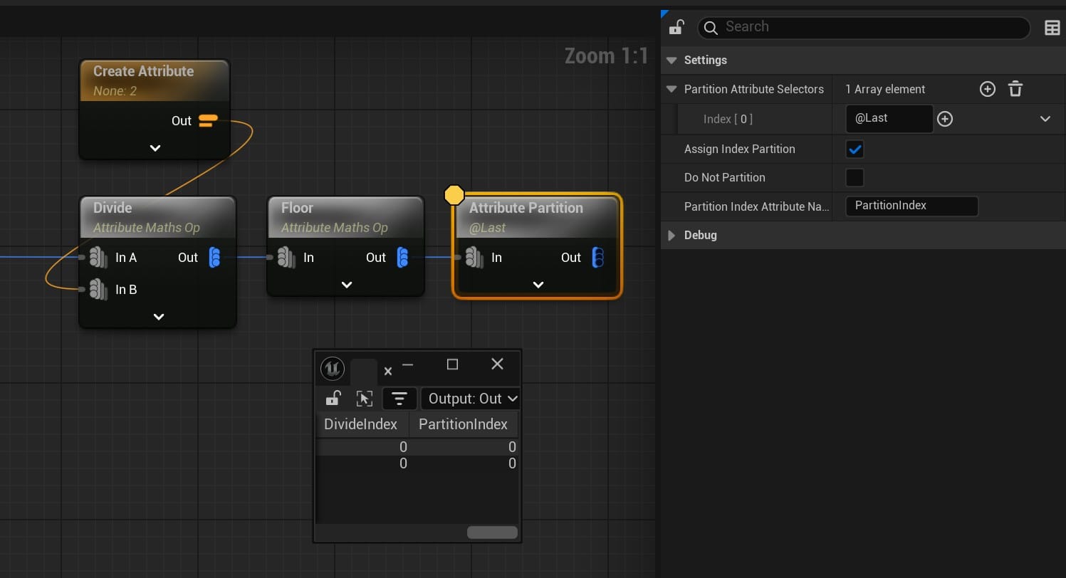
Now, all the socket-points are partitioned into pairs, unless there was an odd number of socket-points, in which case the last socket-point ends up in a partition all by itself and gets ignored :(
The output from the Attribute Partition node could go straight into a Create Spline node and I would have my splines. The problem, in my case, was that depending on the location of the socket-points, many of those splines would cut through the mesh of the metal rack. How could I make it only generate splines between points that have an unobstructed path?
Unobstructed Cable Splines Between the Cable Sockets
There might be a simpler solution to this problem. Also, this is a somewhat strange way to use the Pathfinding node, but it worked.
Like the example in this guide, I think the Pathfinding node is typically used to find a connect-the-dots path through a bed of points, given a start point and a goal point.
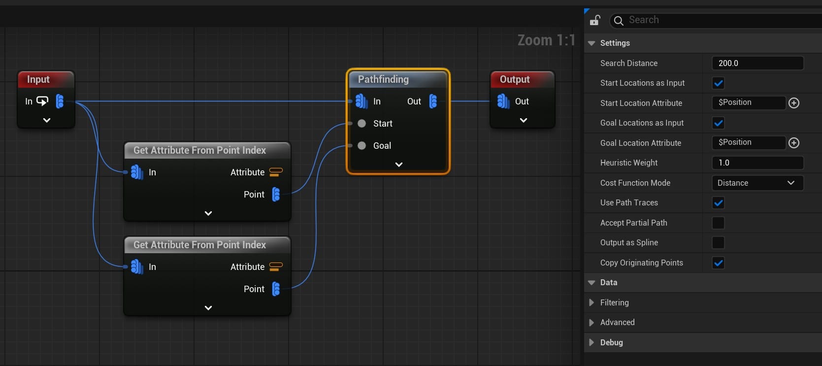
In my case, I just gave it a pair of socket-points and assigned the position of Index 0 to Start and the position of Index 1 to Goal. In the Pathfinding node, the crucial settings were to check "Use Path Traces" and uncheck "Accept Partial Path." The result is that, for a pair of points, if the path trace finds a path (i.e. it isn't blocked by a collision-enabled mesh), it outputs the pair. If it doesn't find a path, it outputs nothing. So, what comes out of the Pathfinding node will be only the pairs it found a path for.
This is the basic idea:
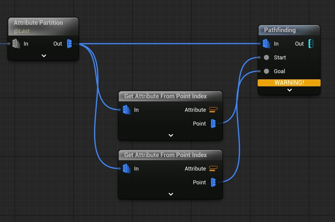
Unfortunately, the basic idea doesn't work. The Pathfinding node didn't know what to do with a long list of point-pairs, so I had to give it one pair at a time using a loop Subgraph:

The custom-made "PCG Pathfinding Loop" node and the graph inside that node.
This loop outputs the unobstructed pairs of socket-points. If some of the partitions have only a single point inside them, the Pathfinding Loop will throw an error, but it will still finish the job.
The Pathfinding node can even create a spline between the output pairs, saving a step. But, I didn't use this option, because it would have generated perfectly straight splines, and I wanted the cables to have some flex.
Curved, Unobstructed Cable Splines Between the Cable Sockets
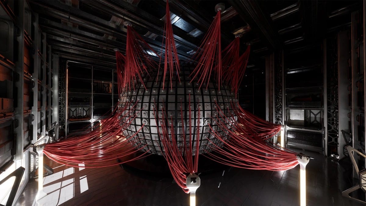
Months before I ventured into procedural generation, I came across the Cassini Sample Project. I knew nothing about PCG, or how they made this:
But, I knew it would be a valuable resource if I ever needed to spawn a bunch of cables in my scene. Actually, I recommend that anyone learning about PCG download the sample project and comb through it. It is also worth watching the talk by Julien L'Heureux and Jean-Sebastien Guay from Unreal Fest Seattle 2024:
My method for adding some curvature to the cable splines was taken from this project. Specifically, their "Geometry" PCG Graph, under the section labeled #6, Wires.
Here is the gist of what they are doing in this section of the graph. A Create Spline node has the option to "Apply Custom Tangents," along with Arrive Tangent and Leave Tangent attributes. I haven't explored how the Arrive and Leave Tangent values work with multi-point splines, but with a two-point spline, it seems straightforward. The Leave Tangent is the angle the spline "leaves" the first spline point, and the Arrive Tangent is the angle the spline "arrives" at the second spline point.
In the #6 Wires section, for each pair of spline points, they create an ArriveTangent and a LeaveTangent variable, run them through a bunch of math nodes, and feed the results into the Create Spline node. I know close to nothing about vector math, so I had to spend the better part of a day inspecting each of these nodes to figure out what they were doing before I could adapt them to my own project. This is my modified version:

The Create Attribute node connected to the Vector: Rotate Around Axis node can be used to adjust the curvature of the two ends of the spline.
While I was at it, I stole their cable mesh, too:

Bonus: Point Lights
In the screenshot at the start of this section, red cables run from points on the sphere up to the ceiling, and also to pylons on the floor level. On the pylons are lights that were procedurally generated. In the Geometry PCG Graph, below the #6 Wires section, there are two nodes labeled "Lights." The Add Component node spawns a point light. I used a similarly-tuned Add Component node in my own project to spawn the accent lights.
Tagging
Quick review: The socket-points created by the Mesh Sockets to Points node are all pooled together with a Merge Points node. Then, they are split into pairs.
By default, I have little control over which points are paired up. The Merge Points node simply appends points in the order the upstream nodes were connected, so socket-points sampled from the same mesh, say Cube_H, are likely to be paired together. Sometimes, this is fine.
But, depending on where the tendril splines are placed on the rack, it is possible to get an unlucky batch, where many point pairs are obstructed by the steel rack and don't spawn a cable, or they are close together and I get too many tiny cables and not enough long ones.
To create groups of socket-points that would generate more interesting cables, I added tags to the tendril-spline Blueprint. One set of tags designated the "level" the spline was placed on the rack. Splines drawn on or around the lowest shelf were tagged "Level1," those on the next shelf were "Level2," and so on. Then, I could use a Filter Data By Tag node to group the socket-points by their level, and pair them only within those groups.
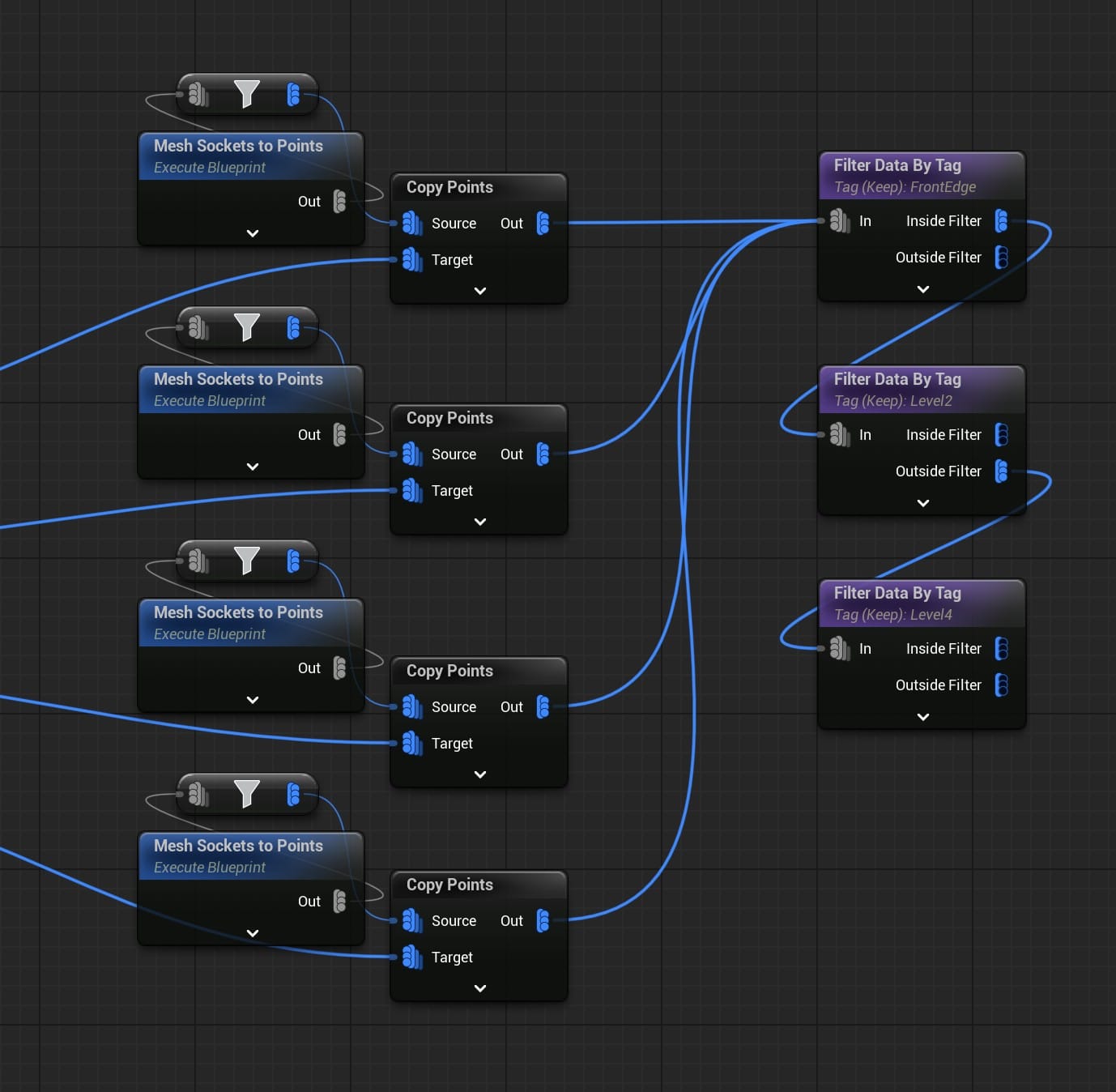
In another case, I had two splines, one running along the front edge of the rack on the fourth level, and one along the front edge of the second level. I wanted cables to spawn only between these two splines, and only vertically between the fourth and second levels, not horizontally within them.
First, I added a "FrontEdge" tag to the splines and used the tag filters to isolate those socket-points, then split them into two groups, Level2 and Level4:
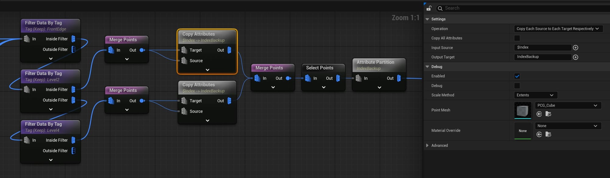
Then, I used an Index-Backup trick (inspired by the Cassini project, again) to pair each socket-point with a point from the opposite group. If there are too many cables, the Select Points node can prune some of them out:
Fun with Procedural Generation
I finally swapped out the brightly-colored placeholder cubes with custom meshes I made using the Unreal Engine modeling tools. I used the cable mesh I cribbed from the Cassini project and I kitbashed the rest from free motherboard assets I found online. My custom meshes aren't great, and I still have a lot of work to do on developing this beast.
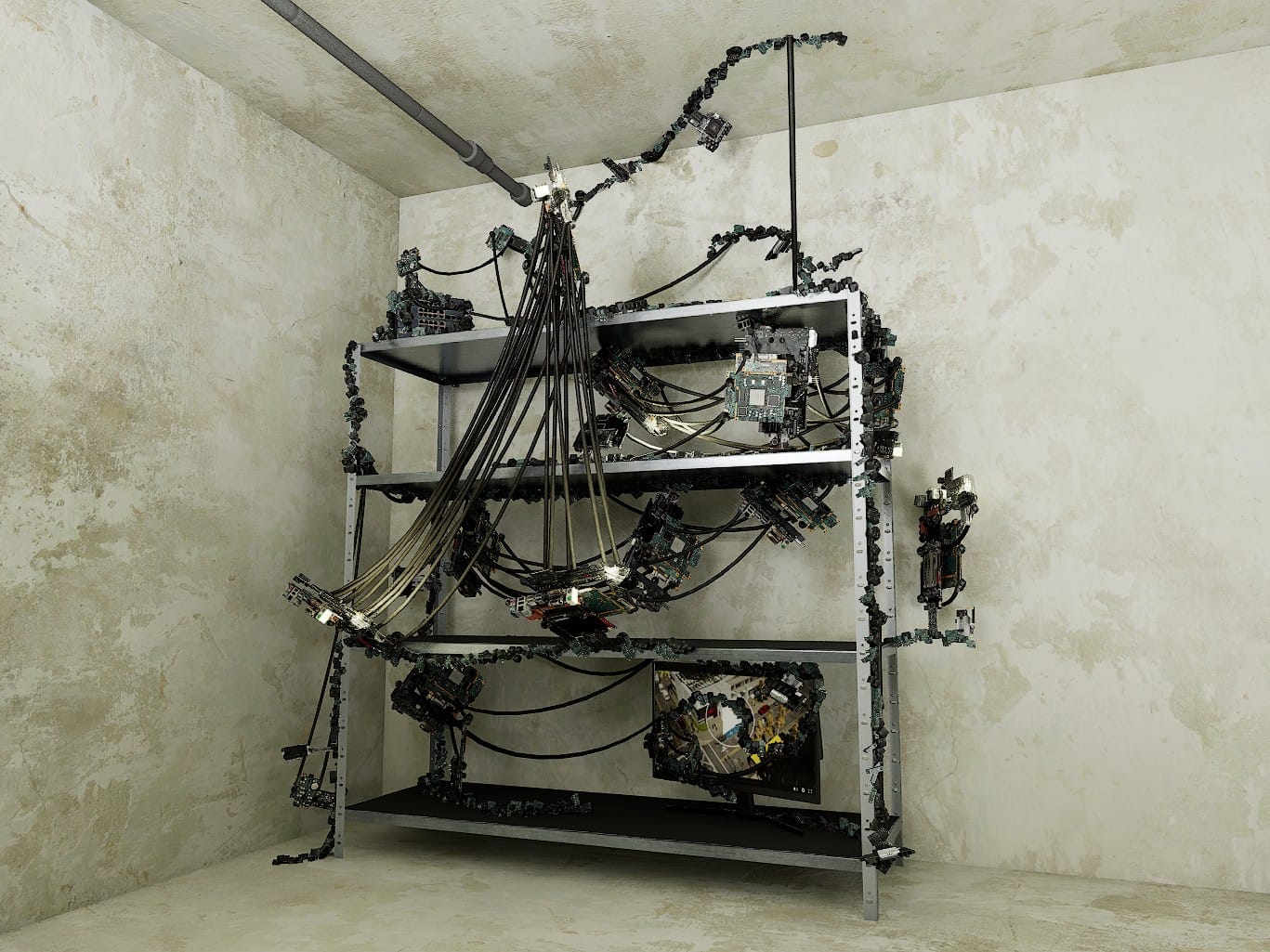
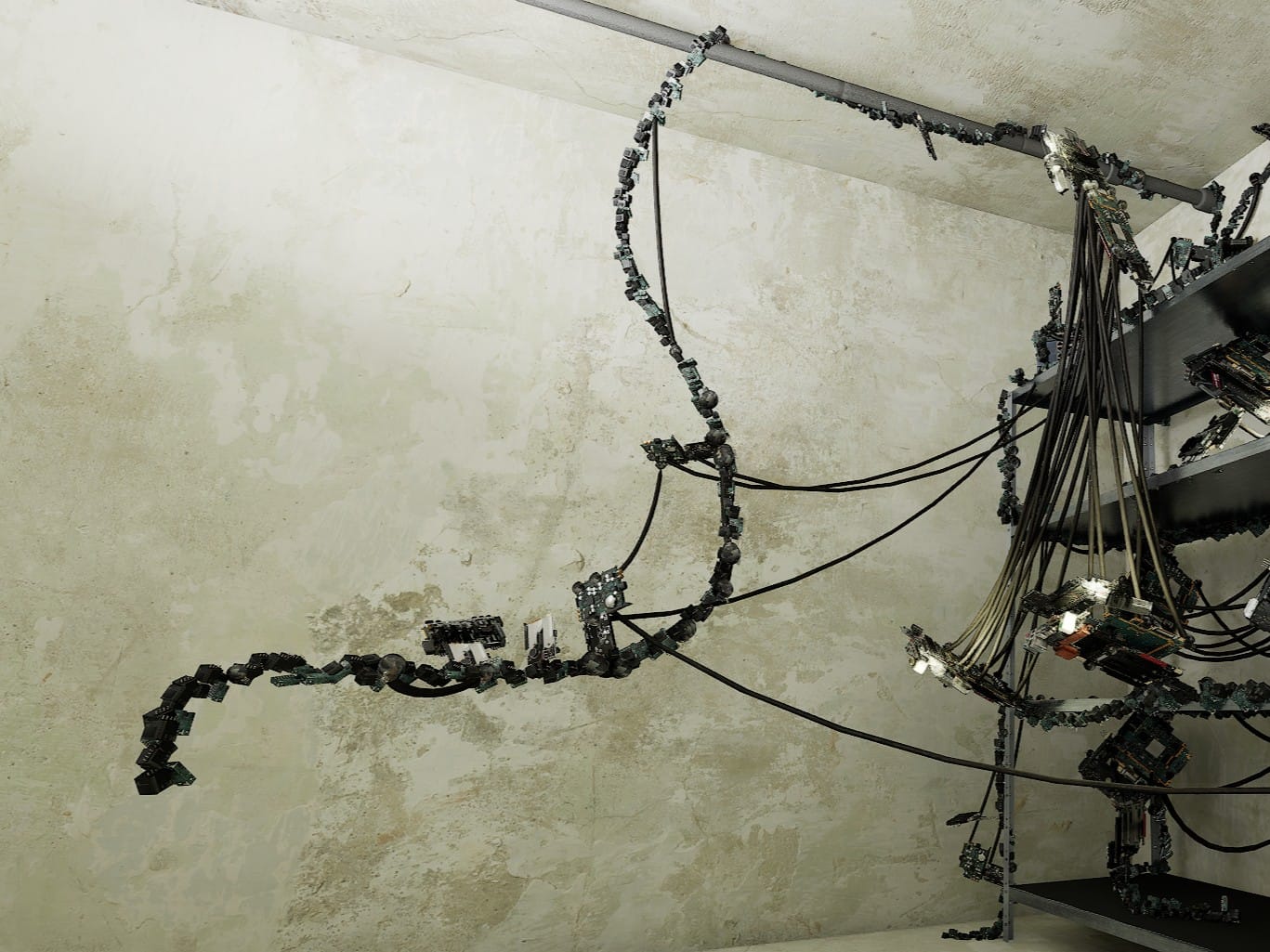
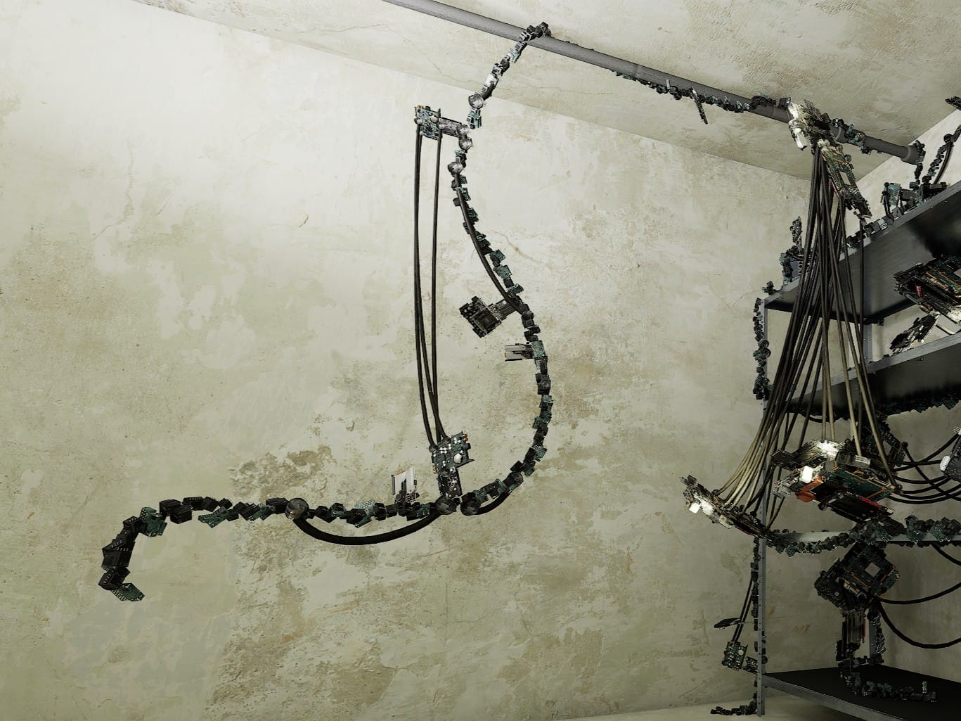
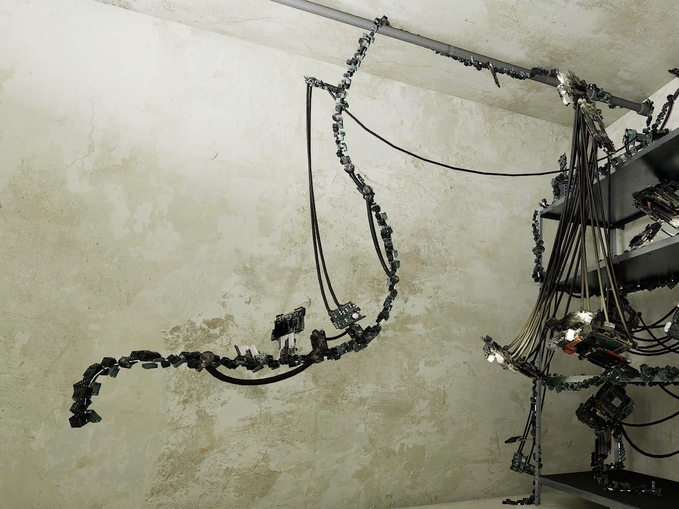
First, I wanted to play around with some lighting setups and create a little scene. I had the idea that a tendril would slither from the rack, along the ceiling, and snake down to connect with one of the character's brains.
The PCG Graph was done, so when I created this spline and tagged it, the PCG Volume immediately picked it up, and as I drew the spline along a pole near the ceiling, the meshes spawned along it. Sometimes, a larger growth would pop up, or a cable should shoot out and attach to the other tendrils on the rack. It was fun to watch! As I pulled the spline along, the PCG randomness kept re-rolling the configurations, so I saw a variety of mesh shapes and cable positions.
Bake a PCG Asset
This whole thing was built in a project dedicated to my PCG experiments. I don't know exactly how Sequencer or Movie Render Queue interact with PCG Graphs, it might be completely smooth, but I decided I didn't want a live PCG Volume in the level I would use for shooting the movie. My plan was to edit the cluster computer in a separate project (or at least a separate level) and move a frozen, or "stamped" version, as a Blueprint, over to the production project.
I used this guide from the Procedural Minds YouTube:
With a Blueprint stamp of a procedural asset, all of the components' settings are available for editing. I could edit the intensity, color, etc. of the point lights originally created by the PCG Graph. So, even in a separate project, I had the flexibility to alter the visuals:
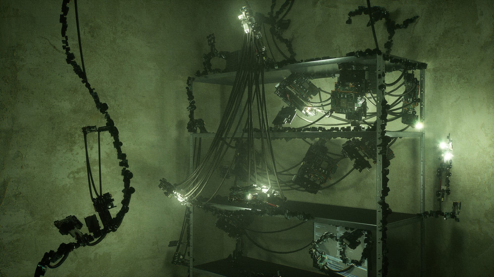
This is a first draft, but I had a blast getting this far and learning about procedural generation. It has been one of the more satisfying sub-projects on this movie.
Things left to do: Find more organic-looking ways to spawn the meshes. Create longer, curvier cables (multi-point splines?). Replace the mesh components with better looking models and better looking shaders. And, who knows what else?